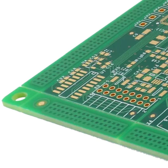
Printed Circuit Boards (PCBs) are manufactured in large quantities for applications ranging from consumer electronics and industrial equipment to automotive systems and communication devices. To turn a PCB design into a physical board, manufacturers need accurate digital information that describes the board structure, electrical connections, dimensions, drilling requirements, and assembly details.
A PCB design created in ECAD software cannot normally be sent directly to manufacturing equipment in its original working format. Instead, the design must be converted into specific production files that the fabricator and assembler can interpret.
So, what file type is used for PCB manufacturing? There is no single file that contains every piece of manufacturing information. Gerber files and NC drill files are commonly used for PCB fabrication, while BOM, Pick and Place, and other files provide additional information required for assembly and inspection.

What is the Importance of File Type in PCB Manufacturing?
The file formats supplied to a PCB manufacturer serve as the communication bridge between the original design and the physical production process. Every manufacturing file contains specific information that must be interpreted correctly by fabrication or assembly equipment.
Using appropriate and complete production files can provide several important benefits.
· Avoid Costly Mistakes During Fabrication and Assembly:
Manufacturing files define critical details such as copper patterns, board outlines, openings, drilling locations, and component positions. Missing or incorrect information can result in a board that does not match the intended design. Correct files help reduce material waste, rework, and production delays.
· Good Communication Channel with Manufacturers:
Designers and PCB manufacturers may use different software platforms and production systems. Standardized file formats allow both sides to exchange design information without requiring the manufacturer to access the designer's original project file. This creates a clearer and more reliable production workflow.
· Increases Efficiency During Fabrication and Assembly:
Digital production files can be imported into CAM, drilling, printing, inspection, and assembly systems. When the supplied data is complete and properly prepared, manufacturers can spend less time requesting clarification and more time preparing the board for production.
· Promotes Quality Control:
Accurate manufacturing data is also important for inspection. Production information can be used as a reference when checking PCB dimensions, copper patterns, solder mask, component placement, and other manufacturing characteristics. This helps manufacturers identify deviations before the finished boards are shipped.
What are the Different Fabrication File Types?
Several file formats can be involved in PCB fabrication, but Gerber and NC drill files are among the most important production files.
Gerber Files:
Gerber files are widely used to describe the graphical information required to manufacture individual PCB layers. Instead of containing the entire PCB project as one file, a typical Gerber output package contains separate files for different board layers and manufacturing features.
Depending on the PCB design, the Gerber package may include the following information:
· Copper Layers:
Copper Gerber files define conductive patterns such as tracks, pads, copper areas, and other features on each layer. Each physical copper layer normally has its own corresponding manufacturing file.
· Solder Mask:
Solder mask files identify the areas where the protective solder mask should be applied and the openings that need to remain exposed for soldering. Accurate solder mask data helps protect copper while ensuring that component pads remain accessible.
· Silkscreen:
Silkscreen files define printed markings on the PCB, including reference designators, labels, symbols, logos, and other identification information. These markings can assist with component placement, assembly, inspection, and later maintenance.
Gerber files are commonly generated by PCB design software and processed through the manufacturer's CAM system before fabrication. File extensions and naming conventions can vary depending on the software and manufacturer, so it is important to follow the fabricator's submission requirements.
Drill Files:
Drill files provide the information required to create holes in the PCB. They can define the location, size, and type of holes used for through-hole components, vias, mounting points, and other board features.
Excellon-format NC drill files are commonly used for this purpose. Drill data is normally supplied together with the Gerber files so the manufacturer can align the hole locations with the copper and other board layers.
What are the other Supporting File Types in PCB Manufacturing?
Fabrication files alone may not provide everything required to assemble a completed PCB. When the project includes component assembly, additional production documents are normally needed.
The required files can vary according to the manufacturer's process and the complexity of the project.
· Bill of Materials (BoM):
The Bill of Materials, or BOM, provides a detailed list of components required for PCB assembly. It can include reference designators, manufacturer part numbers, component values, descriptions, quantities, approved suppliers, and other sourcing information.
A carefully maintained BOM helps the assembly team identify the correct components and reduces the possibility of installing an incorrect part. Whenever a component is replaced or its part number changes, the BOM should be reviewed and synchronized with the latest PCB design.
· Pick and Place Files:
Pick and Place files, also called Centroid files, provide the positional information required by automated assembly equipment. They typically include each component's reference designator, X-Y coordinates, rotation, and side of the PCB.
The information allows pick-and-place machines to accurately position surface-mount components on their corresponding pads. If the PCB layout is changed after these files are generated, the Pick and Place data should also be regenerated to prevent placement errors.
· Netlist Files:
A netlist describes the electrical relationships between components and their connection points. It can identify which pins, pads, and components are connected within the circuit.
Netlist information is useful during PCB design and can also support certain manufacturing and inspection processes. It provides a way to compare the intended electrical connections with the physical board data.
Depending on the design software and manufacturing workflow, netlists may be generated or exported from platforms such as Altium Designer, KiCad, and other ECAD systems.

What are the Challenges in PCB File and Data Exchange?
Even when the PCB design itself is correct, problems can occur if the manufacturing files are incomplete, outdated, or inconsistent with one another. Careful file preparation and review before submission can significantly reduce these issues.
· Incomplete Gerber Layer:
Every required board layer should be included in the manufacturing package. Missing a copper, solder mask, silkscreen, or other required layer can prevent the manufacturer from reproducing the intended PCB structure correctly. A Gerber viewer can be used to review the exported files before they are submitted.
· Inaccurate Component Location:
Incorrect or outdated Pick and Place data can cause components to be installed in the wrong locations or orientations. This can happen when the PCB layout is modified but the assembly files are not regenerated. Designers should ensure that the latest PCB layout and assembly data correspond to the same design revision.
· Vague Naming Convention:
Poorly organized file names can make it difficult for manufacturers to determine which file corresponds to which PCB layer or production function. Clear naming conventions and a structured file package make the manufacturing data easier to identify and process.
· Documentation Issues:
Production problems can also arise when supporting information is incomplete. Examples include missing part numbers, obsolete components, inconsistent BOM data, incorrect revision information, or unclear assembly instructions.
Before sending a PCB project to manufacturing, it is good practice to review the complete production package and confirm that all files represent the same revision of the design. Using a Gerber viewer, checking the board outline, reviewing drill data, and comparing the BOM with the latest schematic can help identify problems before production begins.
Conclusion
So, what file type is used for PCB manufacturing? In most PCB production workflows, Gerber files and NC drill files provide the core information needed to fabricate the bare board, while BOM, Pick and Place, and other supporting files provide the information required for component assembly and inspection.
The exact file package can vary depending on the PCB manufacturer, board technology, and assembly requirements. Therefore, designers should always confirm the manufacturer's preferred formats and submission guidelines before generating the final production package.
A well-prepared set of manufacturing files helps maintain consistency between the original design and the finished PCB, reduces communication problems, and supports a smoother fabrication and assembly process. Working with an experienced PCB manufacturer can further simplify file preparation, engineering review, and production data verification.