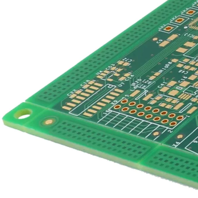
Printed circuit board (PCB) defects can interrupt electrical signals, affect system stability, and prevent electronic devices from operating as intended. Identifying the source of a fault and selecting the appropriate repair method are essential for restoring circuit functionality without introducing additional damage.
PCB repair requires careful diagnosis, suitable tools, and controlled rework procedures. Industry standards and guidelines, including those published by IPC and ANSI, provide important references for workmanship and quality acceptance. As modern circuit boards incorporate smaller components, finer-pitch connections, and increasingly compact layouts, technicians must use more precise inspection and repair techniques.
PCB failures can originate from fabrication defects, component damage, soldering problems, environmental exposure, or assembly process variations. This guide explains how to repair PCB board problems through systematic troubleshooting, common defect correction, and practical considerations for achieving reliable repair results.

What are the Troubleshooting and Fixing Steps when Repairing a PCB?
Effective PCB troubleshooting begins with identifying the symptoms and narrowing down the possible causes. A structured diagnostic process helps technicians avoid unnecessary component replacement and reduces the risk of damaging functional areas during rework.
1. Visual Inspection. Begin by examining the circuit board for visible abnormalities, including cracked components, discolored areas, damaged traces, loose connectors, and solder bridges. Pay particular attention to components showing signs of overheating, such as swollen capacitors, burnt resistors, or darkened PCB material. Inspecting both sides of the board, where accessible, can reveal damage that is not immediately visible. This initial assessment provides a useful starting point for determining how to repair PCB board faults efficiently.
2. Capture Thermal Images. Thermal imaging can help locate abnormal heat generation in components, power distribution circuits, and other areas of the PCB. Comparing temperature patterns with a known-good board or expected operating conditions may reveal short circuits, overloaded components, or inefficient power conversion. Thermal measurements should be performed under controlled conditions by qualified personnel, particularly when the circuit must be energized. Before applying power, check for obvious shorts and other conditions that could make energization unsafe.
3. Run Electrical Tests. Use a digital multimeter to measure supply voltages, check continuity, and investigate suspected short circuits or open connections. An oscilloscope can help evaluate clock signals, switching behavior, and signal waveforms when static measurements do not explain the fault. Resistance measurements may also help identify damaged components, although in-circuit readings can be affected by parallel paths. Combining these tests with the circuit schematic and component specifications makes it easier to isolate the defective area and determine the appropriate PCB troubleshooting procedure.
4. Install New Components. After confirming the source of the failure, replace defective components with compatible parts that meet the original electrical and thermal specifications. Select an appropriate rework method according to the package type, board construction, and component sensitivity. Before installing a replacement, remove residual solder and clean the work area as required. Apply suitable flux or solder paste, position the component correctly, and follow the recommended soldering or reflow profile. Verify component polarity, pin alignment, and orientation before completing the repair.
5. Inspect and Test the Repaired PCB. Once the repair is complete, examine the affected area for solder bridges, incomplete joints, lifted pads, and damage to nearby components or traces. Electrical testing should confirm that the repaired circuit functions within its specified limits. X-ray inspection may be appropriate for certain hidden solder connections, such as bottom-terminated packages and ball grid array (BGA) components, where the joint structure cannot be evaluated visually. If the results do not meet acceptance criteria, further diagnosis and controlled rework may be necessary. Repair limits and inspection requirements should follow the applicable product specifications and workmanship standards.
What are the Top Issues that can be Encountered during PCB Repair?
Circuit board rework can introduce additional defects when heat, mechanical force, or component positioning is not properly controlled. Understanding common repair-related problems helps technicians choose appropriate tools and procedures while protecting the integrity of the original PCB.
· Pad Lifting. PCB pads may separate from the laminate when excessive heat, prolonged soldering, or mechanical force weakens the bond between the copper and the board material. This defect can interrupt electrical connections and make subsequent repairs more complicated. To repair a lifted pad, technicians should first assess the extent of the damage and determine whether the original connection can be restored or a trace repair is required. Suitable low-stress rework methods, controlled heating, and appropriate board preheating where necessary can reduce the risk of further damage. Any replacement pad or jumper connection must meet the circuit's electrical and mechanical requirements.
· Coplanarity Issue. Coplanarity describes how evenly component terminals or contact surfaces align with the intended mounting plane. Uneven component leads, package deformation, board warpage, or inconsistent soldering conditions can prevent some terminals from making reliable contact with their corresponding PCB pads. These problems may lead to open connections, uneven solder joints, or assembly defects. During PCB repair, inspect the component and board for deformation before attempting to remount the part. Appropriate board support, controlled heating, accurate component placement, and compliance with the recommended reflow profile help minimize alignment problems.
· Damaged Component. Electronic components can deteriorate when exposed to excessive temperatures, repeated heating cycles, electrostatic discharge, or mechanical stress during repair. Heat-sensitive devices may develop internal damage even when the external package appears normal. Before replacing a suspected component, verify the fault through electrical measurements or other suitable diagnostic methods. Use a rework profile compatible with the component and PCB assembly, and limit unnecessary heating cycles. Following manufacturer recommendations and documented rework procedures helps preserve surrounding components and reduces the likelihood of recurring failures.

What are the Factors to Consider When Repairing a PCB Board?
The objective of PCB repair is to restore the circuit's required functionality while maintaining appropriate quality, safety, and reliability. Before beginning any repair, technicians should evaluate the following factors to determine the most suitable approach.
· Skills and Training. PCB repair requires knowledge of electronic circuits, component identification, soldering techniques, and fault diagnosis. Personnel should receive appropriate training before working on fine-pitch components, multilayer boards, or assemblies with specialized requirements. Practical experience with rework equipment, temperature control, and inspection methods helps technicians identify defects accurately and avoid damaging adjacent circuitry. For complex repairs, trained specialists with the necessary tools and documented procedures should handle the work.
· Process Controls. A controlled repair process improves consistency and reduces the chance of introducing new defects. Important controls include selecting suitable soldering temperatures, limiting heating duration, applying appropriate flux, maintaining ESD protection, and verifying component orientation before installation. Repair records should identify the original defect, the corrective action taken, and the results of subsequent inspections and tests. Establishing repeatable procedures makes it easier to evaluate repair effectiveness and maintain consistent quality across multiple circuit boards.
· Safety Considerations. Always disconnect the PCB from its power source before conducting resistance, continuity, or component replacement work. Capacitors and other energy-storage components may retain hazardous voltages, so verify that the circuit has been safely discharged before handling it. Use appropriate insulated tools, eye protection, ESD-safe equipment, and suitable ventilation when soldering. Gloves should be selected according to the specific hazard and must not compromise safe handling of hot tools or electrical equipment. When working with high-voltage circuits or specialized electronic systems, follow the applicable safety procedures and ensure that the work is performed by qualified personnel.
· Cost Considerations. Deciding whether to repair or replace a PCB involves more than comparing the price of replacement components. The assessment should include technician labor, diagnostic time, rework equipment, replacement parts, inspection, functional testing, and the possibility of additional failures. Boards with extensive copper damage, severe overheating, or complex multilayer defects may require substantially more effort to restore. Compare the expected repair cost and reliability with the price, availability, and lead time of a replacement board. For production equipment and commercial electronics, downtime and the consequences of a recurring fault should also be considered.
Conclusion
Reliable PCB repair depends on accurate fault identification, appropriate rework techniques, and thorough verification after the repair. From visual inspection and electrical testing to component replacement and final quality checks, each stage contributes to restoring circuit functionality while minimizing the risk of additional damage.
When repairing fine-pitch assemblies, multilayer boards, or circuits with complex component layouts, technicians must pay particular attention to thermal control, pad integrity, ESD protection, and applicable workmanship requirements. A documented repair process helps improve consistency and supports better long-term performance.