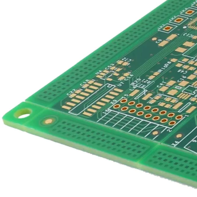
Electronic devices may require component replacement, circuit modifications, or repairs as they age or undergo design improvements. In these situations, removing soldered components without damaging the circuit board is an important skill. Whether you are recovering reusable parts, troubleshooting a faulty circuit, or modifying an existing electronic design, the right desoldering technique can make the process safer and more efficient.
Desoldering requires appropriate tools, controlled heat, and careful handling of the board. Different components and PCB structures may require different removal methods, so choosing the correct approach is essential. This guide explains how to desolder PCB components, reviews common techniques, and outlines the precautions needed to protect the board during rework.

What is PCB Desolder?
PCB desoldering is the process of removing solder from an electrical joint so that a component or connection can be detached from a printed circuit board. It is commonly performed during electronic repairs, component upgrades, prototype modifications, and the recovery of reusable parts from existing assemblies.
The process generally involves heating a solder joint until the solder becomes molten, then removing the liquid solder with a suitable tool. Once the joint has been sufficiently cleared, the component can be released with minimal force. The goal is to remove the component while preserving the surrounding pads, copper traces, and neighboring parts.
The appropriate method depends on the component package, the number of solder joints, the board's thermal characteristics, and the sensitivity of nearby components. A solder sucker or solder wick may be sufficient for many through-hole parts, while hot-air equipment is often better suited to surface-mount devices with multiple terminals. Understanding these differences is the first step toward learning how to desolder PCB assemblies safely and efficiently.
Why is Desoldering Needed?
Desoldering is an important part of PCB maintenance and electronic product development because it allows individual components to be removed without replacing the entire circuit board. When a component fails, technicians can remove it, inspect the affected area, and install a suitable replacement to restore functionality.
The process is also useful during prototyping and product upgrades. Engineers may need to replace components with alternative specifications, correct assembly mistakes, or modify a circuit after testing reveals a design issue. Desoldering makes these adjustments possible while preserving as much of the existing hardware as possible.
Another benefit is resource efficiency. Recovering serviceable components and repairing electronic assemblies can reduce material waste and avoid unnecessary replacement costs. However, reused components should be inspected and tested before installation, particularly when their previous operating conditions are unknown.
As modern circuit boards become smaller and more densely populated, component removal requires greater precision. Proper desoldering techniques help reduce the risk of lifted pads, damaged traces, and heat-related defects, making them valuable for both professional electronics servicing and personal repair projects.
Various Desoldering Techniques
Several techniques can be used to remove solder from a PCB, and each has its own advantages. Before beginning, disconnect the equipment from its power source and allow stored electrical energy to discharge according to the device's service procedures. Use appropriate ESD protection, identify the component to be removed, and select tools suitable for its package and solder joints.
Flux can help solder flow more readily, while a temperature-controlled tool provides better control over heat exposure. The following methods cover common approaches to learning how to desolder PCB components.
1. By Desoldering Pump
A desoldering pump, also called a solder sucker, is commonly used to remove solder from plated through-hole connections. First, apply a small amount of flux if needed, then heat the joint with a soldering iron until the solder melts completely. Position the pump nozzle close to the molten solder and activate the pump to draw the solder away from the hole.
Repeat the process if solder remains, allowing the joint to reheat fully before applying suction again. For stubborn connections, adding a small amount of fresh solder can sometimes improve heat transfer and help the existing solder melt evenly.
This method is relatively affordable and works well for connectors, switches, and other through-hole components. However, it may take several attempts to clear a plated hole completely. Avoid forcing component leads out of the board, as residual solder can damage the plated barrel or surrounding pad.
2. Using a Soldering Iron Setup
A conventional soldering iron is a practical option for removing components with accessible solder joints. Apply flux to the joint, select an appropriate temperature, and place the iron tip against the solder until it melts. The molten solder can then be removed using solder wick or a separate desoldering pump.
Solder wick is particularly useful for cleaning residual solder from pads and removing excess material from surface-mount connections. Place the braid over the joint and touch it with the heated iron; the braid draws molten solder into its woven copper structure.
This approach is inexpensive and suitable for many small repair jobs. Nevertheless, it requires careful control of temperature and contact time. Multilayer PCBs can dissipate heat rapidly, especially around ground planes and large copper areas, so adequate heating and appropriate tools may be necessary. Excessive pressure or prolonged heating can lift pads and damage the laminate.
3. With a Desoldering Gun
A desoldering gun combines a heated tip with a vacuum mechanism, allowing solder to be melted and extracted through the tool. It is especially convenient when working on boards with numerous through-hole joints or when repeated desoldering operations are required.
After the gun reaches its operating temperature, place the tip over the target joint and allow the solder to melt thoroughly. Activate the vacuum to remove the solder, then check whether the component lead can move freely. If the hole remains blocked, repeat the operation rather than pulling the lead out by force.
Compared with a separate iron and pump, a desoldering gun can make repetitive work faster and more consistent. It also reduces the need to coordinate two separate tools. However, the equipment requires regular cleaning and maintenance, and its tip size must match the joint being serviced. Appropriate temperature settings remain essential to prevent unnecessary thermal stress.
4. Hot Air Rework Station
A hot-air rework station is widely used for removing surface-mount components, particularly packages with multiple leads or terminals underneath the component body. Unlike a conventional soldering iron, hot air distributes heat across the component and its solder joints, making it useful when direct tip access is limited.
Begin by selecting a nozzle suitable for the package and applying compatible flux around the solder joints. Set the temperature and airflow according to the component, solder alloy, and board construction. Where appropriate, preheat the PCB to reduce thermal gradients. Direct the hot air evenly around the component until the solder has melted, then lift the part gently with tweezers or a vacuum pickup tool.
Do not pry or twist the component while the solder remains solid. Excessive airflow can displace nearby small components, while excessive temperature can damage sensitive packages, solder mask, or the laminate. For heat-sensitive assemblies, shielding nearby parts and following component-specific rework guidance can help reduce risk.
Hot-air equipment is particularly useful for integrated circuits, connectors, and other SMD packages, but it requires practice to achieve consistent results without affecting surrounding circuitry.
Steps Post Desoldering
After removing a component, the PCB should be inspected and cleaned before any replacement part is installed or the board is powered again. Desoldering may leave residual flux, solder fragments, or partially blocked holes, all of which can interfere with subsequent assembly or electrical testing.
First, examine the affected area under suitable lighting or magnification. Check for lifted pads, damaged solder mask, scratched copper traces, and signs of overheating. For through-hole components, confirm that the holes are sufficiently clear for the replacement leads. For surface-mount pads, remove excess solder carefully so that the new component can sit correctly.
Clean flux residues using a method compatible with the flux chemistry, PCB materials, and component requirements. If a copper trace or pad appears damaged, assess the electrical connection before proceeding; visible damage should not be ignored. A multimeter can help verify continuity where appropriate, although the results must be interpreted in the context of the circuit.
Once the area has been inspected and cleaned, install the replacement component if required and solder it using the correct process. Check the new joints for proper wetting, bridging, and mechanical stability. Before restoring power, verify polarity, component orientation, and the absence of unintended shorts.
These post-desoldering checks help ensure that the repair has not introduced additional faults and that the board is ready for further testing.

Avoiding Common Mistakes in Desoldering
PCB rework requires a balance between sufficient heat to melt solder and minimal exposure to protect the board and components. Poor technique can cause defects that are more difficult to repair than the original problem. Keep the following precautions in mind when learning how to desolder PCB components.
Avoid excessive heat exposure. High temperatures or prolonged contact can lift copper pads, damage nearby components, and weaken the PCB laminate. Use a temperature-controlled tool, select an appropriate setting, and limit heating time as much as possible.
Do not force components from the board. Make sure the solder has melted and the joint is sufficiently clear before moving a component. Pulling against a solid solder connection can tear pads from the substrate or damage plated through-holes.
Remove excess solder carefully. Residual solder may prevent a replacement component from sitting flat or create unwanted bridges between adjacent pads. Use solder wick or a suitable extraction tool without applying excessive pressure.
Apply flux when appropriate. Flux improves solder wetting and helps the solder melt and flow more consistently. Choose a compatible flux type and clean residues when required by the material specifications and intended application.
Protect nearby components. Hot air and direct iron contact can affect adjacent parts, particularly on densely populated boards. Use suitable shielding, an appropriately sized nozzle, and controlled airflow when working around small or heat-sensitive components.
Use ESD precautions and verify the board before powering it. Static-sensitive devices can be damaged during handling. Wear suitable ESD protection, inspect the reworked area, and perform relevant electrical checks before reconnecting power.
Following these practices improves the likelihood of successful component removal while reducing the chance of additional PCB damage.
Conclusion
Desoldering is a valuable technique for repairing electronic assemblies, updating prototypes, and recovering reusable components. Choosing the right tool depends on the component package, solder joint design, and construction of the PCB. A desoldering pump or solder wick is often sufficient for straightforward joints, while a desoldering gun or hot-air rework station can provide greater efficiency for more demanding applications.
Successful results depend on controlled heating, appropriate flux use, careful component handling, and thorough inspection after removal. By following a systematic procedure, technicians and electronics enthusiasts can learn how to desolder PCB components while minimizing damage and improving the reliability of subsequent repairs. For complex multilayer boards, fine-pitch packages, or valuable assemblies, professional rework services may be the safer option.