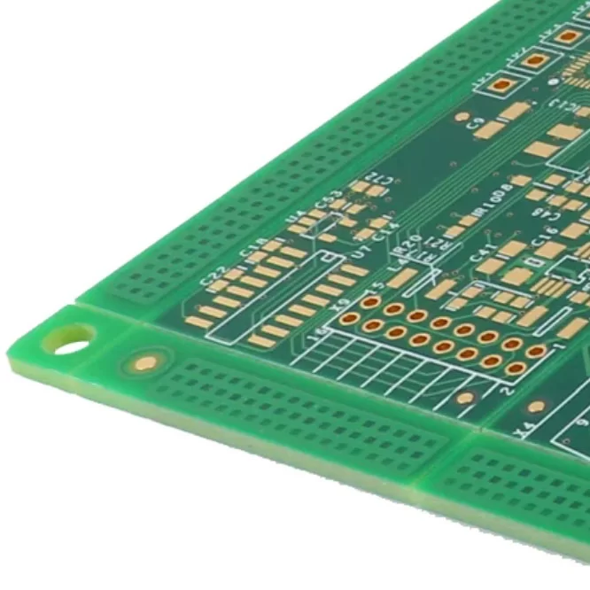
A multimeter is one of the most practical tools for diagnosing electrical problems on a printed circuit board (PCB). It allows technicians, engineers, and electronics enthusiasts to measure key electrical parameters and identify potential component failures without immediately replacing parts. Whether you are assembling a prototype, repairing a damaged circuit, or investigating unexpected device behavior, accurate measurements can make troubleshooting more efficient.
Learning how to check PCB components with a multimeter involves more than placing probes on component terminals. You need to select the appropriate measurement mode, understand the expected electrical characteristics, and account for other components connected to the same circuit. Resistors, capacitors, diodes, transistors, fuses, and inductors can all be examined with a multimeter, although some tests require partial removal or isolation of the component.

What Is Multimeter Testing in PCB Diagnostics?
Multimeter testing is a diagnostic method used to evaluate electrical characteristics within an electronic circuit. Depending on the instrument and test conditions, a digital multimeter can measure resistance, voltage, current, capacitance, continuity, and diode forward voltage. These functions help determine whether a component behaves as expected or whether further investigation is necessary.
PCB component testing is useful during manufacturing quality checks, equipment maintenance, prototype validation, and fault diagnosis. A technician may use resistance measurements to examine a resistor, diode mode to evaluate a semiconductor junction, or continuity mode to check a fuse or conductive path.
Common PCB components that can be examined with a multimeter include:
Resistors
Capacitors
Diodes
Transistors
Fuses
Inductors
Some measurements can be performed while a component remains mounted on the PCB. However, surrounding circuit paths may influence the result. If an in-circuit measurement appears inconsistent with the component's rated value or expected behavior, isolating one terminal or removing the component may be necessary for a more reliable assessment.
Tools and Materials Needed for Testing PCB Components
Preparing suitable equipment before beginning a test helps improve measurement accuracy and reduces unnecessary handling of the circuit board. The tools required depend on the component type, the accessibility of its terminals, and whether testing will be performed on a powered or unpowered circuit.
Important Equipment:
Digital Multimeter (DMM): Choose a meter with resistance, continuity, diode, and voltage functions. A capacitance function is also useful when evaluating capacitors.
Probe Clips or Precision Probes: Insulated probes with fine tips or clips help maintain stable contact with small PCB terminals.
PCB Under Inspection: Ensure the relevant component markings, solder joints, and test points are accessible.
Circuit Schematic or Board Documentation: Schematics and component specifications help establish expected values and identify connections that could affect measurements.
Optional Tools:
Analog Multimeter: Useful for certain conventional measurements where needle movement provides a visual indication of changing values.
Magnifying Glass or Digital Microscope: Helps identify component markings, damaged solder joints, cracked packages, and PCB traces.
Soldering Iron or Desoldering Pump: Allows a component terminal to be disconnected when an in-circuit measurement cannot provide a conclusive result.
ESD Protection Equipment: An antistatic wrist strap and suitable work surface help protect electrostatic-sensitive components.
Tip: An auto-ranging digital multimeter can simplify routine measurements by selecting an appropriate range automatically. Before testing, confirm that the meter and probes are rated for the circuit's voltage and measurement category.
How to Prepare for Multimeter Testing
Correct preparation is essential when checking PCB components. It helps prevent electrical hazards, protects sensitive parts, and reduces the chance of misinterpreting measurements.
1. Turn Off the Circuit Power: Disconnect the power supply before measuring resistance, continuity, capacitance, or diode characteristics. Never use these modes on an energized circuit unless the instrument manufacturer explicitly permits the particular test.
2. Discharge Capacitors Safely: Capacitors may retain hazardous energy after a circuit has been switched off. Use an appropriate resistor or purpose-built discharge tool, following the component's specifications. Verify the remaining voltage with a suitable meter before touching the terminals. Avoid directly shorting a capacitor with a screwdriver or wire.
3. Select the Correct Multimeter Mode: Choose the function that matches the component and the intended test. Resistance mode evaluates resistance, diode mode checks semiconductor junction behavior, and continuity mode identifies low-resistance paths. Voltage measurements require the circuit to be energized only when appropriate and safe.
4. Identify the Component and PCB Layout: Locate the component using its reference designator, markings, schematic, or board documentation. Determine its polarity and pin configuration where relevant. Understanding the surrounding circuit helps explain why an in-circuit reading may differ from the component's standalone value.
Step-by-Step Guide: How to Check PCB Components With a Multimeter
The correct procedure depends on the component being tested. Before interpreting any reading, compare the measured result with the component's specification and consider whether connected circuit paths could influence the measurement.
Testing of Resistors
Resistors limit current and establish voltage relationships within a circuit. Their resistance can be checked using the following steps:
Disconnect the PCB from its power source and ensure that nearby capacitors have been safely discharged.
Set the multimeter to resistance mode (Ω). Select an appropriate range if the meter is not auto-ranging.
Place one probe on each resistor terminal, ensuring good contact with the exposed metal.
Compare the reading with the resistance value indicated by the component's markings, color bands, schematic, or bill of materials.
If the result differs substantially from the expected value, isolate one terminal and measure again before concluding that the resistor is defective.
An in-circuit resistor may appear to have a lower resistance than its rated value because other components create parallel paths. An open or visibly damaged resistor also warrants further inspection, but measurements should always be interpreted in the context of the circuit.
Testing of Capacitors
Capacitors store electrical charge and are used for filtering, energy storage, timing, and signal coupling. A multimeter with a capacitance function can help evaluate whether a capacitor's measured value is within its specified range.
Switch off the circuit and discharge the capacitor safely.
If necessary, disconnect one terminal or remove the capacitor to minimize interference from surrounding components.
Select capacitance mode and connect the probes to the capacitor terminals. Observe polarity when testing polarized capacitors and follow the meter manufacturer's instructions.
Allow the reading to stabilize, then compare the result with the rated capacitance and tolerance.
If the value is substantially outside the permitted range, perform additional checks or use a dedicated component tester where appropriate.
Not every multimeter can measure capacitance. Resistance mode may show a changing reading as a capacitor charges from the meter's test current, but this behavior alone cannot establish whether the capacitor is healthy. A shorted capacitor may show very low resistance, although in-circuit paths can produce similar readings.
Testing of Diode
Diodes are semiconductor devices that conduct primarily in one direction under normal operating conditions. The diode function on a multimeter provides a convenient way to evaluate their forward and reverse behavior.
Disconnect power from the PCB and discharge relevant capacitors.
Set the multimeter to diode mode.
For a conventional silicon diode, place the red probe on the anode and the black probe on the cathode.
Record the forward-voltage reading. Many standard silicon diodes show approximately 0.5–0.8 V, although the expected value varies by diode type and test current.
Reverse the probes. A typical healthy silicon diode should display OL or another open-circuit indication in the reverse direction.
A reading close to zero in both directions may indicate a shorted diode, while an open indication in both directions may suggest an open diode. However, connected circuit paths can affect these results, so isolate the component if the measurements are inconclusive. Schottky diodes, LEDs, and other specialized types may produce different forward-voltage readings.
Testing of Transistor
Transistors are used for switching and amplification, and their test procedure depends on whether the device is a bipolar junction transistor (BJT), MOSFET, or another transistor type. A multimeter's diode function can provide a preliminary check of many conventional BJTs.
Identify the transistor type and locate its base, emitter, and collector terminals using the datasheet or component documentation.
Set the multimeter to diode mode.
For a typical NPN BJT, place the red probe on the base and the black probe on the emitter, then test the base-to-collector junction in the same polarity. Both junctions often show a forward drop around 0.6–0.7 V for a silicon device.
Reverse the probes across each junction. The readings should generally indicate no conduction in the reverse direction.
For a typical PNP BJT, reverse the probe polarity for the corresponding forward-junction tests.
A short or open reading across multiple junctions may indicate damage, but circuit connections can affect the result. MOSFETs have different internal structures and may contain a body diode, so they require a device-specific test procedure. For more detailed diagnosis, use a transistor tester or follow the manufacturer's datasheet.
Testing of the Fuse and Jumpers
Fuses and jumper connections can be checked using continuity mode or low-resistance measurement. These tests help identify broken connections that may interrupt current flow.
Disconnect power and select continuity mode on the multimeter.
Place one probe on each end of the fuse or jumper connection.
A fuse with very low resistance and a continuity indication is generally intact.
An OL or open-circuit indication may mean that the fuse has blown or the connection is broken.
If the reading is unexpected, verify the probe contact and isolate the component when necessary.
A continuity beep does not prove that every connection is suitable for its intended operating current. For example, a damaged fuse holder or poor solder joint may still show continuity while introducing unwanted resistance. Compare measurements with the circuit design and inspect the associated solder joints.
Mistakes to Watch Out For While Testing
Even a reliable multimeter can produce misleading results if the test setup is incorrect. Avoiding common errors helps prevent damage and improves the accuracy of PCB troubleshooting.
Testing Live Circuits in the Wrong Mode: Applying resistance, continuity, or diode mode to an energized circuit can produce false readings and may damage the meter or circuit. Confirm that the board is unpowered before these tests.
Ignoring Stored Capacitor Energy: A powered-off board may still contain charged capacitors. Discharge them using an appropriate method and verify the voltage before handling the circuit.
Overlooking Parallel Circuit Paths: Components connected in parallel can change in-circuit resistance and diode readings. Isolate a terminal or remove the component if the result cannot be explained by the schematic.
Selecting the Wrong Multimeter Setting: Using the wrong mode or input terminal can cause invalid measurements and potentially damage the instrument. Check the dial position, probe sockets, and meter instructions before each test.
Ignoring Component Polarity: Diodes, electrolytic capacitors, and many semiconductor devices have defined terminal configurations. Identify their polarity and pinout before placing the probes.
Using Poor Probe Contact: Oxidation, solder residue, and unstable probe placement can cause fluctuating readings. Ensure the test points are clean and that the probes make reliable contact.

How to Analyse and Troubleshoot Test Results
Interpreting multimeter readings requires more than deciding whether a number looks normal. The component's specifications, surrounding circuitry, test conditions, and instrument limitations should all be considered before identifying a fault.
No Reading or OL: This may indicate an open circuit, a component outside the selected measurement range, poor probe contact, or a measurement mode that is unsuitable for the test. Check the meter settings and probe connections before drawing a conclusion.
Very Low Resistance or a Continuity Beep: A low reading may indicate a shorted component or a normal low-resistance path. Check the schematic and compare the measurement with the circuit's expected behavior. Remember that continuity beeps alone do not confirm a fault.
Unexpected Component Value: An unusual reading may result from parallel components, incorrect identification, poor contact, or a defective part. Verify the component specification and repeat the test with one terminal isolated if necessary.
Fluctuating Measurements: Unstable readings can result from capacitor charging, intermittent contact, residual charge, or a damaged solder joint. Secure the probes, confirm that the circuit is in the correct state, and repeat the test under consistent conditions.
Different Results From the Datasheet: Datasheet values may assume particular temperatures, test currents, or operating conditions. Confirm that the multimeter's test conditions are suitable and use a more specialized instrument if the required parameter cannot be measured reliably.
A suspected defective component should be confirmed through additional testing whenever possible. Replacing a part based on one unexplained reading may fail to resolve the original problem if the real cause is a damaged trace, poor solder joint, or fault elsewhere in the circuit.
Safety Tips for Using a Multimeter on PCBs
Safe testing practices are essential when working with electronic assemblies. Incorrect probe placement or unsuitable meter settings can create electrical hazards, damage components, or compromise the test equipment.
Keep Resistance and Diode Tests on Unpowered Circuits: Disconnect the power supply before checking resistance, continuity, or diode characteristics. Follow the meter manufacturer's instructions for any specialized in-circuit test.
Discharge Capacitors Before Handling: Confirm that stored voltage has been reduced to a safe level before touching terminals or conducting resistance measurements. High-voltage circuits may require specialized procedures.
Use Insulated Probes and ESD Protection: Keep fingers behind the probe guards, use suitable insulated tools, and apply ESD precautions when handling sensitive semiconductor devices.
Measure Voltage Carefully: Select the correct voltage mode and input terminal, verify the meter's rating, and avoid allowing the probes to bridge adjacent contacts. Live measurements should be performed only by people familiar with the relevant electrical hazards.
Check the Meter Before Testing: Inspect leads and probe insulation for damage, confirm the selected mode, and verify that the leads are connected to the correct sockets. Never measure voltage while the lead remains connected to a current input.
Avoid Unnecessary Component Contact: Use stable probe placement and avoid applying excessive force to small terminals, exposed traces, or fragile surface-mount parts.
FAQ
Q1: Can components that are not removed from the PCB be tested?
Yes. Many components can be checked while installed on the board, especially during preliminary troubleshooting. However, parallel connections and other circuit elements may affect the readings. If an in-circuit result is inconsistent with the component's expected behavior, disconnect one terminal or remove the component for a more reliable measurement.
Q2: How do you test resistors using the best multimeter setting?
Set the multimeter to resistance mode (Ω) and place one probe on each resistor terminal while the circuit is unpowered. Compare the result with the component's rated value and tolerance. Auto-ranging meters select a suitable range automatically, while manual-ranging models may require you to begin with a higher range and adjust it for a clearer reading.
Q3: What is wrong with my capacitor when I measure it in resistance mode?
A changing resistance reading can occur because the multimeter is charging the capacitor during the test. This behavior does not necessarily indicate a fault. After safely discharging the capacitor, use capacitance mode if available and compare the result with the specified value. A shorted capacitor may show very low resistance, but in-circuit connections can complicate diagnosis.
Q4: How can I check whether a transistor is functioning?
For a conventional BJT, use diode mode to test the base-emitter and base-collector junctions in both probe directions. A silicon device often shows a forward voltage of approximately 0.6–0.7 V in the conducting direction. Results vary by transistor type, and in-circuit connections can interfere with testing. MOSFETs require a different procedure based on their structure and datasheet.
Conclusion
Learning how to check PCB components with a multimeter is an important skill for electronics troubleshooting, maintenance, and quality verification. By selecting the appropriate measurement mode and understanding the expected behavior of resistors, capacitors, diodes, transistors, and fuses, you can identify potential problems more efficiently and make better-informed repair decisions.
Accurate diagnosis also requires proper preparation, safe handling of stored electrical energy, and awareness of the limitations of in-circuit measurements. When readings are ambiguous, isolating the component and comparing the results with its specifications can help distinguish a genuine component failure from an issue elsewhere on the board.