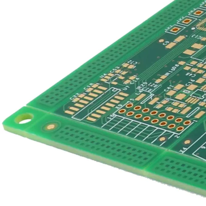
Printed Circuit Boards (PCBs) are the foundation of modern electronic devices, providing both mechanical support and electrical connections for electronic components. Whether used in consumer electronics, industrial equipment, automotive systems, or medical devices, a PCB must operate correctly to ensure reliable product performance. However, manufacturing defects, component failures, physical damage, or environmental factors can all prevent a PCB from functioning as expected.
When an electronic device stops working or behaves abnormally, one of the first troubleshooting tasks is determining whether the PCB itself is operating correctly. Understanding how to check if a PCB is working allows engineers, technicians, and electronics enthusiasts to locate faults efficiently, reduce unnecessary component replacement, and restore equipment to normal operation.

What is PCB Check?
A PCB check is the process of inspecting and testing a printed circuit board to verify that every electrical connection, component, and circuit performs according to its design specifications.
Unlike testing a single electronic component, PCB verification involves examining an entire electrical system. Every resistor, capacitor, integrated circuit, connector, and copper trace contributes to the overall functionality of the board. A failure in any one of these areas may cause the complete system to malfunction.
PCB inspection is performed during multiple stages of a product's lifecycle. Manufacturers inspect newly assembled boards before shipment, maintenance engineers diagnose faulty equipment during repair, and quality control teams verify product consistency throughout production.
Learning how to check if a PCB is working involves combining visual examination with electrical measurements and functional verification. Depending on the complexity of the circuit, testing may range from a simple inspection to advanced diagnostic procedures using specialized equipment.
How to Check if a PCB is Working
A PCB should always be inspected systematically, beginning with basic observations before progressing to electrical and functional testing. This structured approach helps locate faults quickly while minimizing the risk of damaging sensitive components.
1. Visual Inspection
Visual inspection is the first and often the most effective step in PCB troubleshooting because many defects can be identified without applying power.
Carefully examine the entire board under adequate lighting. For densely populated PCBs, use a magnifying glass or microscope to inspect small solder joints and fine-pitch components.
Several areas deserve particular attention.
Physical Damage
Check the PCB for cracked substrates, broken traces, burn marks, warped areas, or signs of mechanical stress. Physical damage often interrupts electrical continuity and may require repair or board replacement.
Inspect Components
Look for components showing signs of overheating, discoloration, swelling, or physical damage. Bulging electrolytic capacitors, cracked integrated circuits, burnt resistors, or damaged connectors frequently indicate circuit failure.
Check Solder Joints
Inspect solder joints carefully for cold solder joints, solder bridges, insufficient solder, lifted pads, or disconnected terminals. Poor solder quality is one of the most common causes of intermittent electrical problems.
Cleanliness Check
Dust, oxidation, moisture, flux residue, and corrosion may create leakage currents or unreliable electrical connections. Ensure the PCB surface is clean before proceeding with electrical testing.
Polarity Check
Verify that polarized components such as electrolytic capacitors, diodes, LEDs, and integrated circuits are installed in the correct orientation. Incorrect polarity can prevent the circuit from functioning and may permanently damage components.
Performing a detailed visual examination often resolves many questions about how to check if a PCB is working before advanced testing becomes necessary.
2. Basic Electrical and Power Check
Once the visual inspection has been completed successfully, electrical testing can begin.
A digital multimeter is one of the most useful diagnostic tools for PCB troubleshooting because it measures continuity, resistance, voltage, and current.
Continuity Check
Set the multimeter to continuity mode and verify that important conductive paths remain electrically connected. Check power rails, signal traces, connectors, and ground connections.
If the multimeter indicates continuity between two points that should remain isolated, a short circuit may be present. Conversely, the absence of continuity where a connection should exist may indicate a broken trace or defective solder joint.
Voltage Measurement
After confirming that no major short circuits exist, apply the correct power supply to the PCB.
Measure voltage at critical locations such as voltage regulator outputs, integrated circuit supply pins, and connector terminals. Compare the measured values with the schematic or design documentation.
Unexpected voltage levels often indicate defective regulators, damaged components, or power distribution issues.
Check the Power Supply Voltage
Before blaming the PCB itself, verify that the external power supply provides the correct output voltage and sufficient current capacity.
Increase the supply voltage gradually if using a laboratory power supply while monitoring current consumption. Excessive current draw frequently indicates short circuits or faulty components.
During this process, regularly observe the PCB for unusual heating or abnormal behavior, which provides additional clues when learning how to check if a PCB is working correctly.

3. Advanced PCB Check
If basic testing cannot locate the fault, more advanced diagnostic techniques may be required.
Oscilloscope
An oscilloscope allows engineers to observe electrical waveforms in real time.
Clock signals, communication buses such as SPI, I²C, UART, and analog signals can be measured directly. Comparing actual waveforms with expected design signals helps identify timing errors, missing clock signals, unstable voltages, and communication failures.
Automated Visual Inspection (AOI)
Automated Optical Inspection systems use high-resolution cameras and image-processing software to compare assembled PCBs with reference designs.
AOI rapidly detects missing components, incorrect orientation, solder defects, and placement errors, making it widely used in high-volume PCB manufacturing.
Thermal Imaging
Thermal cameras reveal abnormal temperature distribution while the PCB operates.
Overheated integrated circuits, voltage regulators, MOSFETs, or shorted traces appear as localized hot spots, allowing technicians to locate faults quickly without physical contact.
X-ray Inspection
Many modern PCBs contain Ball Grid Array (BGA) packages and multilayer structures that cannot be inspected visually.
X-ray imaging reveals hidden solder joints, internal vias, layer connections, and manufacturing defects that would otherwise remain undetected.
Functional Testing
The final verification step is functional testing.
The PCB is installed within its intended system or connected to dedicated testing equipment that simulates actual operating conditions.
Input signals are applied while outputs are monitored to confirm that every function operates according to design requirements.
If all expected functions perform normally, the PCB can generally be considered fully operational. Otherwise, further troubleshooting may be necessary to isolate the remaining fault.