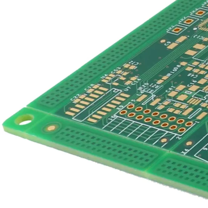
Printed Circuit Boards (PCBs) are found in nearly every modern electronic device, from smartphones and laptops to industrial equipment and medical instruments. While a finished PCB may appear to be nothing more than a board populated with electronic components, it is actually a highly engineered platform that distributes power, transfers signals, and enables electronic circuits to function accurately.
Many people use electronic products every day without considering the technology hidden inside them. Understanding how does a PCB board work helps engineers, manufacturers, and even end users better appreciate how electronic devices process information, control functions, and deliver reliable performance. This article explains the structure of a PCB and explores the working principles behind its operation.

What is a PCB?
A Printed Circuit Board (PCB) is the backbone of an electronic circuit. It provides both mechanical support and electrical connections for electronic components through carefully designed copper pathways.
PCBs are available in different configurations depending on application requirements. Simple electronic products may use single-sided boards, while more advanced systems often require double-sided or multilayer PCBs to accommodate higher component density and more complex circuits.
Rather than simply holding components in place, a PCB is responsible for distributing electrical power, transmitting data signals, and maintaining stable communication between every part of the circuit. When electrical energy enters the board, it travels through conductive traces, interacts with various components, and eventually produces the desired output for the connected device. This complete process explains how does a PCB board work in practical electronic applications.
Structure of a PCB
Although a PCB appears simple from the outside, it is built from several specialized layers that work together to achieve electrical and mechanical reliability.
1. Substrate Layer
The substrate forms the structural foundation of the PCB. It provides rigidity, electrical insulation, and mechanical support for all conductive layers and mounted components.
Most rigid PCBs use fiberglass-reinforced epoxy resin (FR-4), which offers excellent strength, thermal stability, and electrical insulation. Flexible PCBs, on the other hand, commonly use polyimide material, allowing the circuit to bend repeatedly without affecting electrical performance.
A high-quality substrate ensures that the board remains dimensionally stable during manufacturing and long-term operation.
2. Copper Layer
Copper is the conductive material responsible for carrying electrical current and digital signals throughout the PCB.
During manufacturing, thin copper sheets are laminated onto the substrate. Chemical etching removes unnecessary copper, leaving only the precisely designed traces required by the circuit.
Trace width, spacing, and thickness are carefully calculated to meet current-carrying capacity, impedance control, and signal integrity requirements. Multilayer PCBs include multiple copper layers separated by insulating materials, enabling more sophisticated circuit routing while maintaining a compact board size.
The copper network forms the electrical highway that demonstrates how does a PCB board work by connecting every component together.
3. Solder Mask
Once the copper circuitry is completed, a protective solder mask is applied over the board surface.
The solder mask prevents accidental short circuits, protects copper from oxidation, and limits solder application to designated pads during component assembly. Although green is the most recognizable color, solder masks are also available in black, blue, red, white, and other colors depending on design preferences.
Besides improving reliability, the solder mask also enhances the durability and appearance of the finished PCB.
4. Components
Electronic components transform a bare PCB into a functional electronic system.
Passive components such as resistors, capacitors, and inductors regulate electrical behavior by controlling current, storing energy, and filtering signals. Active components—including transistors, integrated circuits, and microcontrollers—perform processing, switching, amplification, and control functions.
Components may be installed using Through-Hole Technology (PTH) or Surface Mount Technology (SMT), depending on product requirements. Their coordinated operation determines the overall functionality of the PCB.
5. Holes & Vias
Holes and vias create electrical connections between different sections of the PCB.
Through holes allow traditional leaded components to be mounted securely, while plated vias connect copper layers inside multilayer boards. Depending on design complexity, vias may be through vias, blind vias, or buried vias.
These vertical electrical pathways enable signals and power to move efficiently between multiple circuit layers, making complex PCB designs possible.
6. Terminals and Connectors
Every PCB needs a method to communicate with external devices.
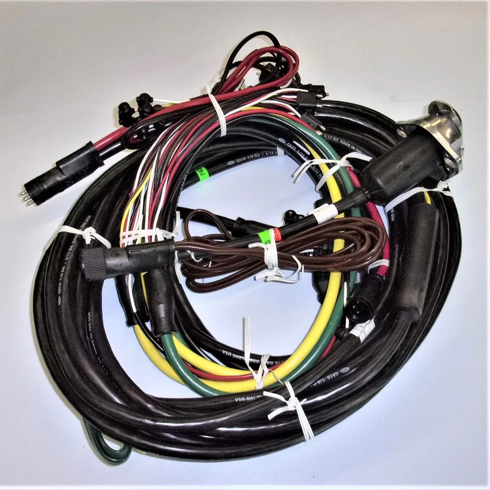
Terminals and connectors provide interfaces for power input, signal transmission, communication modules, displays, sensors, and peripheral equipment. Some applications also include ribbon cable connectors, edge connectors, or wire harnesses to simplify system integration.
Reliable connector design ensures stable communication between the PCB and the complete electronic product.
7. Silkscreen
The silkscreen is the printed identification layer located on the outer surface of the PCB.
It contains component reference designators, polarity indicators, pin numbers, company logos, test points, and assembly instructions. Although it does not participate in electrical operation, the silkscreen significantly improves manufacturing efficiency, maintenance, troubleshooting, and quality inspection.
For technicians, the silkscreen serves as a valuable guide during PCB assembly and repair.
Working Principle of PCB
The operation of a PCB depends on the coordinated interaction between conductive traces, electronic components, and external power sources. Each section contributes to the board's ability to process electrical energy and digital information efficiently.

Electrical Continuity
Electrical continuity forms the basis of every PCB circuit.
When power is supplied, copper traces distribute voltage and current to every component according to the circuit design. Continuous electrical pathways ensure that energy reaches each device without interruption.
Engineers carefully design trace routing to eliminate open circuits, excessive resistance, short circuits, and unnecessary interference. Stable electrical continuity is one of the most fundamental concepts in understanding how does a PCB board work.
Signal Routing
In addition to power delivery, PCBs must accurately transmit digital and analog signals.
Input signals received from sensors, switches, communication modules, or external equipment travel through dedicated signal traces toward processing components such as microcontrollers, processors, or programmable logic devices.
After processing, output signals are directed to displays, motors, communication interfaces, or other controlled devices. Careful signal routing minimizes electromagnetic interference (EMI), signal loss, and timing errors, ensuring reliable system performance.
Component Response
Every electronic component performs a specific electrical function within the circuit.
Resistors regulate current flow and voltage levels. Capacitors temporarily store electrical energy while filtering noise. Inductors manage magnetic energy in power circuits. Diodes allow current to flow in only one direction, protecting sensitive components. Transistors operate as electronic switches or amplifiers, while integrated circuits execute complex calculations and control logic.
The interaction between these components transforms incoming electrical energy into useful functions that power modern electronic products.
Feedback Mechanism
Many electronic systems include feedback circuits that continuously monitor system performance.
Sensors detect voltage, current, temperature, speed, pressure, or other operating conditions and send feedback signals to the control circuitry. The processor compares actual operating conditions with the desired values and automatically adjusts outputs whenever necessary.
This closed-loop control improves accuracy, efficiency, and long-term reliability in industrial automation, power management, automotive electronics, robotics, and consumer products.
The feedback mechanism demonstrates another important aspect of how does a PCB board work by enabling intelligent system regulation rather than simple electrical connections..