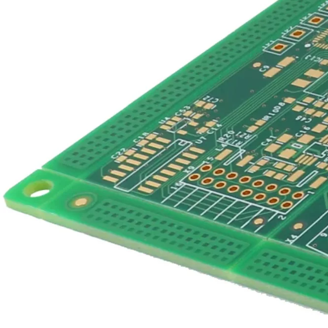
Printed Circuit Boards (PCBs) are built by integrating electronic components, copper traces, and insulating materials into a complete electrical system. Every resistor, capacitor, integrated circuit, transistor, connector, and diode performs a specific function within the circuit. If even one component fails, the entire PCB may experience unstable operation, reduced performance, or complete failure.
Whether troubleshooting an electronic product during maintenance or verifying a newly assembled board, identifying defective components accurately is a critical skill. Understanding how to find faulty components on PCBs enables engineers and technicians to locate faults quickly, minimize unnecessary repairs, and restore equipment to normal operation.

What are PCB Faults?
A PCB fault refers to any condition that prevents the circuit from operating according to its intended design.
Faults may originate from manufacturing defects, damaged components, incorrect assembly, poor soldering, electrical overstress, environmental influences, or aging during long-term operation.
The most common PCB faults include open circuits, short circuits, defective electronic components, damaged copper traces, lifted pads, poor solder joints, and unstable operating conditions.
Since modern PCBs integrate hundreds or even thousands of interconnected components, locating the exact source of failure requires a systematic troubleshooting process. Learning how to find faulty components on PCBs helps technicians isolate problems efficiently while avoiding unnecessary component replacement.
Frequent Faulty Components on the PCB
Although every PCB design is unique, certain electronic components fail more frequently than others due to their electrical characteristics or operating environment.
Electrolytic capacitors may dry out or bulge after prolonged exposure to heat, resulting in unstable power supplies or excessive ripple voltage.
Resistors may become open-circuit or change resistance values because of overload conditions.
Semiconductor devices such as diodes, MOSFETs, transistors, and integrated circuits are vulnerable to excessive voltage, current surges, electrostatic discharge (ESD), and overheating.
Connectors and switches may develop poor contact because of oxidation, vibration, or repeated insertion cycles.
Inductors and transformers may suffer insulation degradation or winding damage under excessive electrical stress.
Recognizing the typical failure characteristics of these components allows engineers to narrow the troubleshooting process and better understand how to find faulty components on PCBs without examining every part individually.
Tools Required for Faulty Component Finding
Accurate fault diagnosis depends heavily on using the appropriate testing equipment.
Basic troubleshooting usually begins with a digital multimeter capable of measuring voltage, resistance, continuity, and current.
A soldering station and desoldering tools are useful when components must be removed for further testing or replacement.
Magnifying lamps or inspection microscopes help identify damaged solder joints, cracked components, and microscopic defects.
More advanced diagnostics often require specialized instruments.
Oscilloscopes display signal waveforms and timing information.
LCR meters measure inductance, capacitance, and resistance with greater precision.
Bench power supplies provide adjustable voltage and current limiting during testing.
Thermal imaging cameras identify overheating components without physical contact.
For multilayer PCBs or hidden solder joints beneath BGA packages, X-ray inspection systems reveal internal defects that cannot be observed visually.
Selecting suitable equipment greatly improves efficiency when learning how to find faulty components on PCBs.

Various Methods for Faulty Component Finding
Successful PCB troubleshooting follows a logical sequence that begins with simple observations before progressing to advanced measurements.
Before testing the board itself, always verify that the external power source, cables, connectors, and operating environment are functioning correctly. Incorrect supply voltage or wiring errors can easily mimic PCB failures.
1. Visual Inspection
Visual inspection is the fastest and most cost-effective diagnostic method.
Carefully examine the PCB under bright lighting or with magnification.
Look for burnt areas, cracked packages, swollen capacitors, lifted copper pads, broken connectors, missing components, damaged traces, corrosion, contamination, and poor solder joints.
Cold solder joints, solder bridges, or improperly aligned components frequently cause intermittent failures that can be identified without applying power.
For many repair cases, visual inspection immediately reveals the faulty component.
2. Electrical Testing Methods
If no obvious physical defects are found, electrical testing should be performed.
Connect the PCB to a regulated laboratory power supply while monitoring current consumption carefully.
Measure important voltage points using a digital multimeter and compare the readings with the schematic or design documentation.
Unexpected voltage drops, unstable outputs, or excessive current draw often indicate defective regulators, short circuits, or failed components.
Signal measurements also help identify which functional section of the PCB is no longer operating correctly.
These electrical tests provide valuable information for determining how to find faulty components on PCBs accurately.
3. Component-based Testing
After identifying the suspected circuit area, individual components should be tested.
Resistors can be checked for correct resistance values.
Capacitors should be evaluated for capacitance, leakage current, or Equivalent Series Resistance (ESR).
Diodes and transistors may be tested using diode-test functions on a multimeter.
Integrated circuits are often verified by checking their supply voltages, input signals, and output responses.
LCR meters, semiconductor analyzers, and dedicated component testers provide more accurate measurements when components must be removed from the PCB.
Testing each component individually allows technicians to confirm the actual source of failure before replacement.
4. Signal Tracing
Signal tracing is particularly useful for complex digital and analog circuits.
Every PCB contains dedicated power distribution paths and signal routing between components. Interruptions anywhere along these pathways may prevent proper circuit operation.
Using an oscilloscope or logic analyzer, technicians can follow signal flow from the input connector through processing circuits to the final output stage.
If a signal disappears or becomes distorted at a particular component, that area becomes the primary focus for further investigation.
Signal tracing helps engineers master how to find faulty components on PCBs without replacing functioning parts unnecessarily.
5. Thermal Testing
Many electronic failures are directly related to excessive heat.
During operation, defective components often generate abnormal temperatures because of internal damage or excessive current consumption.
Infrared thermal cameras quickly reveal localized hot spots on voltage regulators, power transistors, integrated circuits, or shorted traces.
Temperature measurements can also verify whether cooling systems, heat sinks, airflow, and thermal interfaces are functioning correctly.
Thermal analysis provides another effective method for locating hidden faults that may not be apparent through visual inspection alone.
Proper Approach for PCB Component Fault Identification
Successful PCB troubleshooting depends on following a structured engineering process rather than replacing components randomly.
Always begin by reviewing the circuit schematic, PCB layout, and manufacturer documentation before performing repairs.
Disconnect power completely and allow capacitors to discharge before handling the board. Use appropriate ESD protection, including grounded workstations and anti-static wrist straps, to prevent additional component damage.
Document every observation, measurement, and repair step throughout the troubleshooting process. Accurate records simplify future maintenance and help identify recurring manufacturing issues.
Start with the simplest diagnostic methods before progressing to more advanced equipment. Many PCB faults can be identified through careful observation and basic electrical measurements.
When a defective component has been confirmed, replace it with an identical or manufacturer-approved equivalent rather than attempting temporary repairs.
Finally, avoid excessive soldering or repeated rework, as unnecessary heating may damage surrounding components or weaken PCB reliability.
Following these best practices makes how to find faulty components on PCBs a more efficient, accurate, and repeatable process.