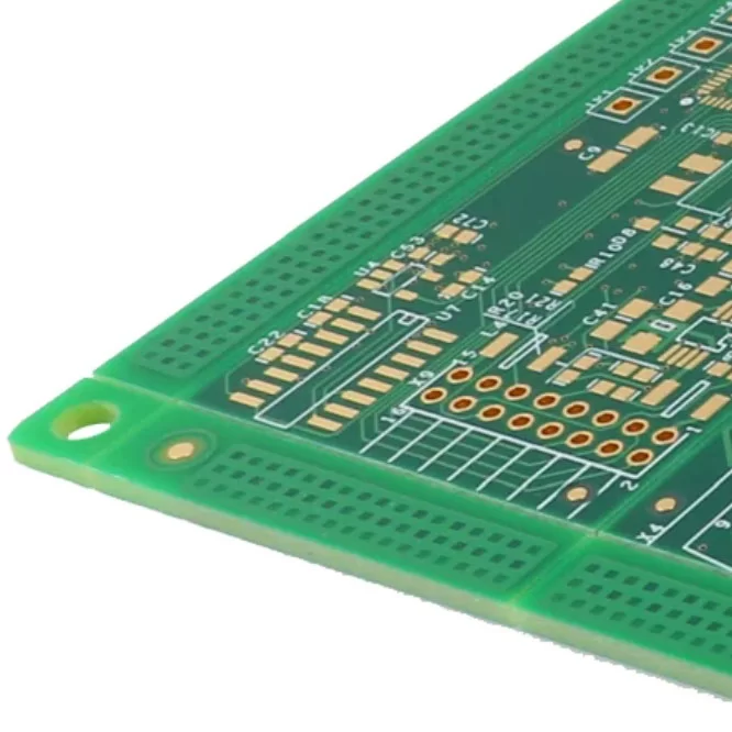
In modern electronic equipment, the Printed Circuit Board (PCB) serves as the foundation that connects electronic components and enables electrical signals and power to move through the circuit. When a device experiences unexpected shutdowns, unstable performance, or complete failure, the PCB is often one of the areas that needs to be examined.
Knowing how to check if a PCB is working can help identify electrical faults, damaged components, connection problems, and other issues before they cause further damage. PCB testing can range from a simple visual inspection to detailed electrical measurements and functional testing.

What is PCB Check?
A PCB check is a systematic process used to determine whether a circuit board and its components are in good condition and operating according to the design requirements. Because a PCB contains multiple interconnected components, traces, solder joints, connectors, and power circuits, a fault in one area can affect the performance of the entire board.
PCB inspection and testing can be performed during manufacturing, after assembly, or when troubleshooting an electronic product. Common problems include short circuits, open circuits, damaged components, poor solder joints, incorrect component placement, and abnormal electrical signals.
The testing method depends on the complexity and application of the PCB. Some basic problems can be identified through visual inspection and multimeter measurements, while more complicated faults may require oscilloscopes, automated inspection systems, thermal cameras, or X-ray equipment.
Understanding how to check if a PCB is working therefore involves using different testing methods at different stages to confirm that the board is both physically intact and electrically functional.
How to Check if a PCB is Working
Since a PCB contains many interconnected components and circuit paths, a single test method may not reveal every possible fault. A reliable PCB check normally starts with a physical examination before moving on to electrical measurements and more advanced diagnostic procedures.
The following methods can be used to evaluate the condition of a PCB and determine whether it is functioning correctly.
1. Visual Inspection
A visual inspection is usually the first step when checking a PCB. It should be completed before power is applied to the board, particularly when a serious electrical fault is suspected. A magnifying glass or inspection microscope can be useful for examining small components and solder connections.
· Physical Damage:
Examine the PCB surface for cracks, broken sections, scratches, burn marks, or damaged traces. Physical damage may interrupt electrical connections or affect the structural integrity of the board.
· Inspect Components:
Check resistors, capacitors, ICs, diodes, connectors, and other components for signs of overheating, discoloration, swelling, cracking, or physical displacement. A visibly damaged component may indicate an electrical or thermal problem.
· Check Solder Joints:
Inspect soldered connections for incomplete joints, cracks, solder bridges, or insufficient solder. Poor soldering can create intermittent connections and may prevent individual components from operating correctly.
· Cleanliness Check:
Look for dust, dirt, moisture, oxidation, or corrosion on the PCB. Contamination can reduce insulation performance and, in some situations, create unwanted conductive paths between circuit areas.
· Polarity Check:
Verify that polarized components, including electrolytic capacitors, diodes, LEDs, and certain connectors, have been installed in the correct orientation. Incorrect polarity can prevent a circuit from operating or may damage the component when power is applied.
2. Basic Electrical and Power Check
Once the PCB has passed the initial visual inspection, electrical testing can be performed. A digital multimeter is one of the most practical tools for basic PCB troubleshooting because it can measure resistance, continuity, voltage, and, depending on the model, current.
When learning how to check if a PCB is working, electrical measurements provide useful information about whether power is reaching the correct sections of the circuit and whether unexpected connections exist.
· Continuity Check:
Use the continuity function to examine circuit traces, connectors, fuses, and other electrical paths. This can help identify broken traces or unintended connections. When checking power and ground areas, an unexpected low-resistance connection may indicate a possible short circuit. The board should remain unpowered during resistance and continuity testing unless the equipment specifically requires otherwise.
· Voltage Measurement:
With the PCB powered under appropriate conditions, measure voltage at important test points and compare the results with the values specified by the circuit schematic or manufacturer documentation. An incorrect voltage may point to a faulty regulator, damaged component, power problem, or another circuit abnormality.
· Check the Power Supply Voltage:
Before connecting a PCB to a power source, verify that the supply voltage matches the board's required input. After powering the board, check important voltage rails such as regulator outputs and IC supply pins. Monitor the board for unusual heat, unexpected current consumption, or other abnormal behavior during the test.
These basic measurements can often narrow down the location of a fault before more advanced testing is required.
3. Advanced PCB Check
When visual inspection and basic electrical measurements do not provide enough information, advanced PCB testing methods can be used. These techniques are particularly useful for complex boards containing high-speed signals, densely populated components, multilayer structures, or difficult-to-access connections.
1. Oscilloscope:
An oscilloscope can display electrical waveforms in real time, making it useful for examining clock signals, power ripple, data transmission, and communication lines. Engineers can compare measured waveforms, frequencies, and signal levels with the expected design values to identify abnormal behavior. Logic analyzers can also be useful when examining digital communication protocols such as SPI, I²C, and UART.
2. Automated Visual Inspection (AOI):
Automated Optical Inspection (AOI) uses cameras and image-processing software to examine assembled PCBs. The system can compare the actual board with predefined inspection criteria and identify issues such as missing components, incorrect component placement, soldering defects, and other visible assembly problems. AOI is especially valuable in high-volume PCB manufacturing because it provides consistent inspection across large numbers of boards.
3. Thermal Imaging:
A thermal imaging camera can reveal unusual temperature patterns while a PCB is operating. Components or circuit areas that become significantly hotter than expected may indicate excessive current, a short circuit, inefficient power conversion, or component failure. Thermal inspection allows technicians to locate potential problem areas without physically touching the board.
4. X-ray Inspection:
X-ray inspection is useful for examining PCB features that cannot be easily observed from the surface. It can help identify hidden solder joints, internal connections, voids, component placement issues, and defects underneath packages or other components. This makes X-ray inspection particularly useful for boards with complex assemblies and concealed solder connections.
5. Functional Testing:
Functional testing evaluates the PCB under its intended operating conditions. The complete circuit or electronic device is powered and its expected functions are checked according to predefined requirements. Input signals, outputs, communication functions, controls, and other operating characteristics can be evaluated during this process.
A successful functional test provides strong evidence that the PCB is performing its intended role. If the board still behaves abnormally, additional component-level or signal-level testing may be necessary to identify the underlying problem.
Conclusion
Knowing how to check if a PCB is working is an important part of electronic troubleshooting, maintenance, and quality control. A reliable inspection process should not depend on a single test. Instead, visual inspection, continuity checks, voltage measurements, signal analysis, thermal inspection, and functional testing can be combined according to the complexity of the PCB and the suspected fault.
For simple circuit boards, a careful visual examination and multimeter test may be enough to identify common problems. More sophisticated electronic assemblies may require oscilloscopes, AOI systems, thermal imaging, X-ray inspection, or specialized functional testing equipment.
By following a systematic PCB testing process, technicians and engineers can locate faults more efficiently, reduce unnecessary component replacement, and improve the reliability of electronic products. Proper testing is therefore an important step not only when repairing a defective PCB but also when verifying the quality and performance of newly manufactured electronic assemblies.