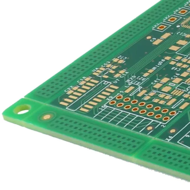
A Printed Circuit Board (PCB) brings multiple electronic components together through carefully designed circuits and conductive traces. When the board is operating normally, each component performs its intended function and works together with the rest of the circuit. However, the failure of a single resistor, capacitor, diode, IC, connector, or other component can affect the performance of the entire system.
When an electronic product shows abnormal behavior, identifying the source of the problem is an important part of troubleshooting. Knowing how to find faulty components on PCBs allows engineers and technicians to narrow down the affected area, verify suspected components, and determine whether replacement or further repair is necessary.
A systematic diagnostic process is generally more effective than replacing components at random. By combining visual inspection, electrical measurements, signal analysis, and thermal testing, potential faults can be located more efficiently while reducing unnecessary work on the PCB.

What are PCB Faults?
PCB faults refer to conditions that prevent a circuit board from operating according to its intended design. These problems can occur in electronic components, conductive traces, solder joints, connectors, or other parts of the board.
Common PCB faults include open circuits, short circuits, incorrect component values, damaged components, poor solder connections, broken traces, and problems caused by unsuitable operating conditions. Manufacturing and assembly errors can also introduce defects that become noticeable only after the PCB is powered or placed under a specific load.
Because components are interconnected through circuit paths, a failure in one section may affect other parts of the board. For example, a defective power component can cause several downstream circuits to receive an incorrect voltage, making the original fault appear to be located somewhere else.
For this reason, PCB troubleshooting should focus on finding the actual source of the abnormal behavior rather than simply replacing the first component that appears suspicious.
Frequent Faulty Components on the PCB
Electronic components on a PCB have different electrical characteristics, operating limits, and failure modes. Understanding the role of each component can make troubleshooting more efficient.
Resistors may experience changes in resistance, overheating, or physical damage. Capacitors can fail because of aging, excessive voltage, heat, or mechanical stress, sometimes resulting in swelling or leakage. Inductors may develop winding or connection problems, while diodes can fail through short or open conditions.
Transistors and integrated circuits (ICs) may stop working because of electrical overstress, excessive temperature, incorrect voltage, or internal damage. Connectors can also create intermittent problems when contacts become loose, oxidized, contaminated, or mechanically damaged.
When learning how to find faulty components on PCBs, it is useful to understand both the normal operating characteristics of these components and the symptoms associated with their failure. Comparing measured values with the PCB schematic, datasheet, or known-good board can provide valuable clues during diagnosis.
Tools Required for Faulty Component Finding
Effective PCB troubleshooting requires the right tools for the type of fault being investigated. Basic problems can often be examined with simple instruments, while complex boards may require specialized diagnostic equipment.
A digital multimeter is one of the most commonly used tools. It can measure resistance, voltage, continuity, and other electrical parameters to help identify open connections, short circuits, and abnormal component values.
A soldering iron and desoldering equipment may be required when a component needs to be isolated or removed for individual testing. A magnifying glass or inspection microscope can help reveal damaged components, cracked solder joints, tiny bridges, and other physical defects.
For more advanced troubleshooting, engineers may use a bench power supply, oscilloscope, LCR meter, component tester, or circuit test fixture. Thermal cameras and infrared inspection equipment can reveal unusual temperature patterns, while X-ray systems can be useful for examining hidden solder joints and internal assembly structures.
Selecting the appropriate equipment is an important part of understanding how to find faulty components on PCBs, because different failure types require different diagnostic approaches.
Various Methods for Faulty Component Finding
Before testing individual components, it is important to understand the symptoms of the PCB and the conditions under which the problem occurs. Check the input power, polarity, connectors, external wiring, and operating environment first. A board that appears to have a component failure may actually be affected by an incorrect power connection, damaged cable, excessive load, or unsuitable operating condition.
Once these basic factors have been verified, the following methods can be used to locate potential faults.
1. Visual Inspection
Visual inspection should normally be the starting point because it does not require the PCB to be powered and can reveal obvious problems quickly.
Examine the board for burned areas, cracked components, swollen capacitors, damaged connectors, missing components, broken traces, corrosion, contamination, and unusual discoloration. Solder joints should also be checked for cracks, insufficient solder, solder bridges, or other assembly defects.
Comparing the actual PCB with its schematic, assembly drawing, or reference board can make it easier to identify incorrect component placement or missing parts. Although visual inspection cannot detect every electrical fault, it can often narrow down the area that requires further testing.
2. Electrical Testing Methods
If no obvious physical problem is found, electrical testing can provide more detailed information about the condition of the circuit.
A multimeter can be used to check continuity, resistance, and voltage at selected test points. When the PCB is powered, measured voltages can be compared with the expected values specified in the circuit documentation. An abnormal voltage may indicate a problem with a regulator, power rail, component, or connected circuit.
For more complex boards, a controlled power supply and test fixture can be used to monitor current consumption and operating behavior. Unexpectedly high current, unstable voltage, or abnormal output signals can help identify the section of the PCB that requires closer examination.
3. Component-based Testing
After identifying a suspicious circuit area, individual components can be tested to determine whether they are operating within their expected specifications.
Resistance measurements can be used for resistors and certain circuit paths, while an LCR meter can provide more detailed information about inductors and capacitors. Diodes and transistors can also be checked using appropriate multimeter functions or dedicated component testers.
For some components, in-circuit measurements may be affected by surrounding components. In such cases, the suspected component may need to be isolated or removed before an accurate measurement can be made.
An oscilloscope can provide additional information when the suspected fault involves changing signals, timing, oscillation, or communication lines. This approach helps distinguish between a defective component and a problem caused by another part of the circuit.
4. Signal Tracing
Signal tracing is useful when a PCB contains multiple interconnected circuit stages and the location of the failure is not immediately obvious.
Start by reviewing the schematic and identifying the expected signal path from the input through each circuit stage to the output. Check the relevant power and signal lines for continuity and then examine the signal at important test points.
An oscilloscope or logic analyzer can be used to observe whether the expected waveform, frequency, voltage level, or digital data is present. If a signal is correct at one stage but becomes abnormal at the next stage, the components and connections between those points become potential areas for further investigation.
This method is particularly useful for PCBs containing processors, communication interfaces, switching circuits, amplifiers, and other signal-dependent systems.
5. Thermal Testing
Temperature can provide important clues when a component is overloaded, shorted, or operating outside its normal conditions.
During controlled operation, a thermal imaging camera or infrared thermometer can be used to observe temperature differences across the PCB. A component that becomes significantly hotter than surrounding components may require further investigation.
Thermal testing can be particularly helpful for identifying problems involving power ICs, regulators, MOSFETs, resistors, capacitors, and other components that dissipate heat during operation.
However, temperature readings should always be interpreted according to the component's normal operating range. A component that is warm is not necessarily defective, so thermal information should be combined with electrical measurements and circuit documentation before reaching a conclusion.

Proper Approach for PCB Component Fault Identification
Finding a faulty PCB component should follow a controlled diagnostic process rather than relying on guesswork. Improper testing, excessive heating, or unnecessary component removal can introduce additional damage and make the original problem more difficult to identify.
Several practices can help improve the troubleshooting process:
· Refer to the correct documentation:
Use the official schematic, PCB layout, component specifications, and assembly information whenever available. Working from an incorrect diagram can lead to inaccurate measurements and unnecessary component replacement.
· Follow electrical safety procedures:
Disconnect the power before performing resistance or continuity measurements. Allow capacitors to discharge properly and use appropriate ESD protection when handling sensitive electronic components.
· Record test results:
Document measured voltages, resistance values, temperature readings, and observed symptoms. Keeping a record makes it easier to compare different test points and identify patterns.
· Begin with simple checks:
Start with power supply, connectors, visible damage, polarity, and basic continuity before moving to more complicated signal analysis. Many PCB problems can be narrowed down through straightforward checks.
· Verify the replacement component:
When a defective component has been confirmed, replace it with a suitable component that meets the required electrical and physical specifications. Check its value, rating, package, polarity, and other relevant parameters before installation.
· Avoid unnecessary rework:
Repeated soldering, desoldering, probing, or modification can damage pads and traces. Perform only the tests and repairs necessary to locate and correct the fault.
Summary
Learning how to find faulty components on PCBs requires a combination of observation, electrical testing, circuit knowledge, and systematic troubleshooting. A PCB fault may originate from a damaged component, broken trace, poor solder joint, power problem, or another condition, so replacing components without proper diagnosis can easily lead to unnecessary work.
A practical troubleshooting sequence is to begin with visual inspection, verify the power and electrical conditions, test suspicious components, trace important signals, and use thermal analysis or advanced instruments when necessary.
As PCB designs become smaller and more sophisticated, professional diagnostic equipment can provide additional information that cannot be obtained through basic inspection alone. By following a structured testing process and referring to accurate circuit documentation, engineers and technicians can locate defective components more efficiently and maintain the reliability of PCB assemblies.